


Pressure transducer and transmitter calibration
.png)
Main Content
- What are Pressure Transducers & Transmitters?
- Introduction
- Principles of Operation
- Application
- Pressure Transducer & Transmitter - Calibration procedure
Pressure transducers and transmitters, also known as pressure sensors, are widely used in various industrial fields. They play a crucial role in controlling pressure for precise operation and ensuring the safety of machinery systems within factories
1. What are pressure transducers & transmitters?
1.1 What are pressure transducers & transmitters?
Pressure transducers and transmitters, often referred to as pressure sensors, are devices that convert pressure into an electrical signal. This signal is then sent back to the controllers for processing.
The three main components of these devices are:
- Transmitter
- Transducer
- Sensor
A transducer is a device that converts energy from one form to another. This component functions to receive signals from sensors and perform processing to convert these signals into another form of signal (usually an electrical signal). For example, a pressure transducer converts pressure into an electrical signal.
A transmitter is a device that receives a signal from a sensor or transducer and converts it into a standard signal such as 4-20mA, 0-5VDC, or 0-10VDC. This conversion allows the signal to be recognized and processed by a controller. The transmitter can also amplify the signal at the same time.
2. Introduction
Pressure sensors, also known as pressure transducers or pressure transmitters, are crucial devices in automatic monitoring and measurement systems in various industries. Pressure sensors can be classified by their measurement modes and their structure. Each type has its unique characteristics and is suited for specific applications.
- Pressure transducers and transmitters can be categorized into two types based on their function: absolute pressure sensors and relative pressure sensors. Absolute pressure sensors take perfect vacuum pressure as their reference point for measurements. On the other hand, relative pressure sensors use the atmospheric pressure as their standard of measurement.
- Based on the principle of measurement, sensors can be categorized into two types: pressure measurement sensors and differential pressure measurement sensors.
- Based on the measurement environment, sensors can be categorized into two types: membrane pressure sensors and non-membrane pressure sensors.
3. Operating Principle
While there are numerous types of pressure sensors available, they all fundamentally operate on the same principle:
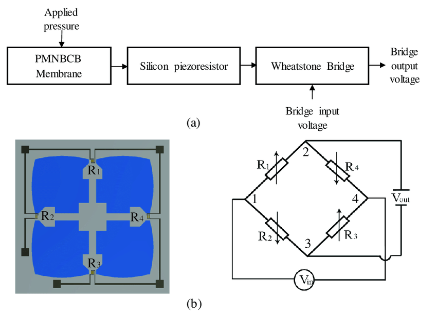
- Each sensor is equipped with a probe that features a membrane layer composed of stainless steel and silicon. This membrane layer is sensitive to changes in pressure. When the ambient pressure fluctuates, the membrane layer expands and contracts in response. A microprocessor within the sensor probe monitors this expansion and contraction process, subsequently generating a pressure signal that it sends to a transducer.
- The transducer's role is to receive this pressure signal and transform it into an electrical signal. This electrical signal is then relayed to a signal transmitter.
- The signal transmitter amplifies the electrical signal into a standard signal, typically ranging from 4 - 20mA or 0 -10V. This signal is then sent to a controller. The controller interprets and processes this signal to control various devices such as valves or pumps, thereby optimizing the production process.
![]()
4. Application
Pressure transducers & transmitters, also known as pressure sensor, are widely used in various industries, particularly in automation. They play a crucial role in controlling pressure for precise regulation. There are many applications such as:
- They are used to measure the pressure in tanks, containers, or water pipes to control the internal pressure of the water tank.
- They are used to measure the output pressure of the air compressor system, ensuring that the air pressure is always within the permissible limit.
- They are used to measure and monitor the internal pressure of the boiler, which can reach several hundred degrees under relatively high temperature and pressure conditions.
- They are equipped in car tires as a safety warning system. The sensor will issue a timely warning when the pressure in the car tire changes suddenly, either higher or lower than the ideal level.
- ............
These are just a few examples of the many applications of pressure sensors. They are essential tools in many fields, contributing to safety, efficiency, and precision.
5. Calibration procedure
The technical document ĐLVN 112: 2002 outlines the sequence, procedures, methods, and means for pressure transducer and transmitter calibration. The following is a summary presentation of the calibration procedure:
- The standards used are piston pressure gauges, liquid pressure gauges, spring-type pressure gauges, and digital pressure gauges. The upper measurement limit of these standard gauges should not be less than the upper measurement limit of the pressure transducer or transmitter that needs to be calibrated
- The relative error of the standard must be less than or equal to one-fourth of the permissible relative error of the pressure transducer or transmitter that needs to be calibrated.
The permissible error of a pressure transducer or transmitter to be calibrated is determined by the formula:
Permissible error = ± Accuracy (%)
- Direct current (DC) power supply: 0~50 VDC, voltage stability: ± 0.2V
- Direct current (DC) voltmeter: 0~20V with an error less than half of the permissible error of the pressure transducer or transmitter that needs to be calibrated
- Direct current ammeter: 0~100mA with an error less than half of the permissible error of the pressure transducer or transmitter that needs to be calibrated
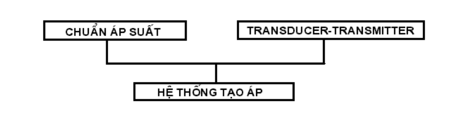
- The pressure generation system must be sealed, increase or decrease pressure evenly, and must be able to generate a minimum pressure equal to 125% of the upper measurement limit of the pressure transducer or transmitter that needs to be calibrated. The pressure should increase or decrease evenly and the pressure drop should not exceed 5% of that limit within 5 minutes.
- Thermometer with suitable measurement range and error not greater than ± 0.5 oC; Hygrometer with suitable measurement range and error not greater than ± 5 %RH.
- For common pressure transducers and transmitters, refer to Table 2.
| Table 2 |
|
The upper measurement limit of the pressure transducer & transmitter to be calibrated (MPa) |
Pressure transmission medium |
|
|
Allow the pressure transmission environment to be converted from gas to liquid if this conversion does not cause an error greater than 10% of the allowable error of the pressure transducer and transmitter.
- For pressure transducers and transmitters used in an oxygen environment, according to Table 3. It is permissible to use gas-liquid, liquid-gas, and liquid-liquid separation chambers for calibration.
| Table 3 |
|
The upper measurement limit of the pressure transducer & transmitter (MPa) |
Pressure transmission medium |
|
|
- When using a liquid as the pressure transmission medium in a calibration system, it’s crucial to prevent air from entering the system.
5.2.1.2 Environmental Conditions
- Ambient temperature:
- (20 ± 2)°C for pressure transducers or transmitters with a relative error < 0.4%
- (20 ± 5)°C for pressure transducers or transmitters with a relative error ≥ 0.4%
- Relative humidity should be less than 80%RH
- The calibration room must be well-ventilated, dust-free, and not heated from one side. It should also be free from vibrations and shocks.
- Both the pressure transducer and transmitter to be calibrated and the standard gauge should be kept in the calibration room until they reach the specified temperature.
- Check the oil level in the pressure pump or standard device, balance the niveau (if using a standard piston pressure gauge), and remove all air bubbles from the device.
- Clean the connector of the pressure transducer and transmitter that needs to be calibrated and install it in the position on the pressure-generating device as follows:
- For a pressure transducer and transmitter to be calibrated, the following information must be fully recorded on its face:
- Serial number;
- Pressure measurement range;
- Electric signal measurement range;
- Supply voltage;
- Measurement unit;
- Pressure transmission environment (for special gases)
The unit of pressure measurement is Pascal (Pa), multiples of Pascal, bar and its subunits, especially millibar (mbar). Other pressure units are used, engraved on the instrument, in accordance with the pressure measurement unit specified in Decree 65/2001/NĐ-CP.
The electrical output signal must increase or decrease regularly according to the increase or decrease of the input pressure.
The pressure transducer and transmitter should be calibrated at a minimum number of points evenly distributed over the entire measurement range when increasing and decreasing pressure, depending on the accuracy level:
- Accuracy level lower than 0.25: The minimum number of calibration points is 10 points;
- Accuracy level from 0.25 to 1: The minimum number of calibration points is 6 points;
- Accuracy level higher than 1: The minimum number of calibration points is 5 points;
The pressure transducer and transmitter must be supplied with the correct voltage according to the manufacturer's specifications.
The standard and the pressure transducer and transmitter must be calibrated on the same horizontal plane. If there is a height difference, the pressure value due to the height of the liquid column must be corrected.
ΔP = ρgh
Where:
ρ : density of the liquid, (kg/m3);
g : acceleration due to gravity at the calibration location, (m/s2);
h : height difference of the liquid column input of the standard pressure gauge and the pressure gauge to be calibrated, (m);
ΔP : pressure to be corrected, (Pa).
5.3.3.2 Checking steps
- Calculate the equivalent conversion value from the pressure unit to the electrical signal unit.
- Power on to heat the pressure transducer and transmitter that needs to be calibrated according to the time required by the manufacturer and the user unit.
- Gradually increase the pressure to the upper measurement limit of the pressure transducer that needs to be calibrated, lock the valve, and maintain for 5 minutes, then check the pressure leakage in the system. Next, slowly open the valve so that the pressure returns to its original state. Open all valves to return the pressure to 0 and record the corresponding voltage or current number into the calibration record.
- Gradually increase the pressure according to each predetermined measurement point and record the corresponding voltage or current signal number.
- When the pressure reaches the upper value of the transducer, lock all valves of the pressure generating system so that the transducer is loaded for 5 minutes. After loading, gradually reduce the pressure according to the value of each measurement point and record the corresponding number. (When reducing pressure, it must not exceed the pressure value at each specified measurement point)
- The calibration result must be recorded in the calibration record
- Calibration formula:
y = a + bx
Where:
x: is the output voltage value of the pressure transducer that needs to be calibrated
y: is the standard pressure value
- Calculate the relative measurement uncertainty
- Type A relative measurement uncertainty
- Type B relative measurement uncertainty is divided into 2 components: Relative measurement uncertainty of the pressure standard and relative measurement uncertainty of the voltmeter or ammeter
- Calculate the combined relative measurement uncertainty
- Calculate the expanded relative measurement uncertainty.
Pressure transducer and transmitter after calibration are issued a calibration certificate with calibration results. The certificate must include the following parameters:
- Calibration formula;
- Expanded or relative measurement uncertainty (%);
- Coverage factor k;
- Confidence level;
- Environmental conditions at the calibration location
Recommended calibration cycle: 01 year
To consult and request a quote for our pressure calibration services, please kindly contact us via the following information:
LABORATORY: DONG TAM MEASUREMENT AND TECHNICAL TRADING SERVICE CO., LTD
ADDRESS: No.57-59 Street 11, Binh Hung Residential Area, Binh Hung Commune, Binh Chanh District, Ho Chi Minh City
TEL: 028 375 83 869 - Hotline: 0909 347 891 (Mr. Lâm)
Email: info@dongtam-mes.vn
Relative post | Xem tất cả
- Stopwatches calibration
- ORP meter calibration
- Hydrometer calibration
- Analytical and Technical balance calibration
- Analytical and Technical balance verification
- Spring dial scales verification
- Spring dial scales calibration
- Bench weight scale verification
- Bench weight scales calibration
- Platform scales verification
- Platform scales calibration
- Chlorine meter calibration
 Legal
Legal  Call: 0283.7583869
  Search for Certificate
  Contact