


Digital and analog temperature indicator calibration
Main content
- About the digital and analog temperature sensors
- Structure and operating discipline
- Why should you calibrate the digital and analog temperature sensor?
- Calibration procedure
Most types of temperature sensors are widely used today in industrial parks or production machinery. However, most of them are not equipped with screens to display measured values. That's why we need to use a temperature display/indicator.
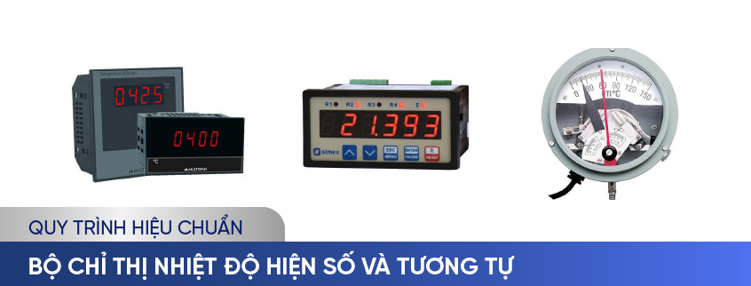
1.1 What is a digital temperature indicator?
- Digital temperature indicator: is a type of indicator that uses numbers to represent temperature values.
- This set of indicators has the advantage of being easy to see and read without being affected by environmental factors. However, this indicator also has the disadvantage of being inaccurate when the measurement range is large or when there is a large temperature change.
1.2 What is an analog temperature indicator?
- Analog temperature indicator: is a type of indicator that uses lines to represent temperature values.
- This indicator has the advantage of being more accurate when the measuring range is large or when there are large temperature variations. However, this set of indicators also has disadvantages: it is difficult to see, difficult to read, and may lose digits or friction.
The main components:
- Temperature sensor: detects heat transfer in a system or environment and converts it into an electrical signal.
- Microcontroller: receives the electrical signal from the sensor and processes it into a digital value. (digital temperature indicator)
- Display: displays digital values of temperature in Celsius or Fahrenheit scale.
- Digital temperature indicators: use electrical principles to detect temperature values, they work by converting the electrical signal it receives from the sensor into a reading in temperature units.
- Analog temperature indicator: uses the physical properties of materials to measure temperature changes.
3. Why should you calibrate the digital and analog temperature indicator?
Analog and digital temperature indicators or any other temperature measuring device after a long period of operation, or due to aging, the device will gradually lose stability and become inaccurate. At this point the device needs to be calibrated. Regularly calibrating the temperature indicator helps:
- Provide accurate and reliable temperature measurements of the environment or product.
- Test and verify the consistency of this device under various conditions.
- Comply with technical and legal requirements of related industries, such as electronics, mechanical, chemical, medical, etc.
Calibration frequency depends on device usage and application.
4. Calibration procedure
The order, procedures, methods and means of calibrating digital and analog temperature indicators have been specified in technical documents ĐLVN 160: 2005. Below is a summary of the calibration procedure for digital and analog temperature indicators.
- The device generates a standard signal with a measuring range appropriate to the temperature range to be calibrated, and has been calibrated according to the ITS-90 International Temperature Scale. Standard signal generating devices may include:
- Standard resistance box;
Standard resistance generator;
Standard mV DC voltage generator;
Standard temperature transmitter;
- Calibrated temperature compensation wires, resistance wires or conductors.
- The measurement uncertainty of the standard combination (including standard signal generator, compensation wire, resistor wire...) must be less than 1/3 of the standard measurement uncertainty of the device to be calibrated.
4.1.2 Auxiliary means
- Standard equipment mounting system and indicators need to be calibrated according to technical requirements.
- Optical system with magnification not less than 4 times
- Gloves, cleaning solution, cotton cloth.....
When performing calibration, the following conditions must be met:
- Ambient temperature: (23 ± 2)°C
- Environmental humidity: (60 ± 10) %RH
(When calibrating temperature indicators in the field, the environmental conditions must satisfy the technical requirements of the device to be calibrated)
- Clean the equipment that needs to be calibrated
- Mount and connect wires according to the technical specifications of the device to be calibrated.
- Select and prepare appropriate standard combinations.
- Symbols and labels on the device must include indicator type, scale, measuring range, accuracy level, manufacturing facility, production number, etc.
- Wire connectors must ensure solid, safe wiring and good contact; The housing protects the indicator from damage.
- If the indicator uses batteries, the batteries must be replaced with new ones that meet technical requirements before performing the test
- For digital display indicators, when power is applied, the displayed numbers must be clear, not blurred or out of focus, and the functions operate normally according to technical specifications.
- For similar types of indicators, the graduation lines must be complete, not blurred or missing digits, and the indicator needle must move smoothly and not get stuck.
- Compares the readings of the device to be calibrated (UUT) with the standard temperature value determined by the standard combination.
- The number of test points N must be divided equally and not less than 3 points in the temperature range to be calibrated.
- With a digital indicator, the test points are temperature values in the tens or even hundreds depending on the measurement range.
- With analog indicators, the test points are numbered lines on the scale.
- Assemble standard equipment and detectors according to technical requirements
- Operate the standard combination according to the equipment instructions.
- Supply power and input signal source to the UUT according to the graduation characteristics, technical requirements, and instructions for using the device.
- Calibrate in the direction of increasing temperature, and adjust the device that provides the input signal so that the indicator of the detector gradually increases to the temperature value corresponding to the lowest first test point in the temperature range to be calibrated.
- When the readings are stable, read and record the temperature readings of the standard and UUT combination. Reading order in order:
Standard ----> Equipment to be calibrated ----> Standard ----> Equipment to be calibrated ---->............
The number of readings at each test point is not less than 3
- Proceed with the above steps sequentially for the next checkpoints until the final checkpoint.
- Calibrate in the direction of decreasing temperature, from the highest point to the lowest point in the temperature range to be calibrated in the order above.
- Calculate the measured average temperature value in the increasing and decreasing direction at each test point of the standard and UUT.
- Calculate the standard deviation in the increasing and decreasing direction at each test point of the standard and UUT
- Calculate the correction number in the increasing direction at each test point of the UUT: equal to the difference between the average value of the corrected standard temperature and the average value of the UUT
- Calculate the error response at each test point of the UUT: equal to the difference between the temperature measurement value measured in the increasing direction and the temperature value measured in the decreasing direction.
- The Measurement of Uncertainty of the calibration result of a digital or similar indicator is calculated according to the following components:
- Measurement of Uncertainty of the standard combination, including the following components:
- Specifications of standard signal-generating equipment (type B)
- Condition of compensation wire or resistance wire (type B)
- Uncertainty due to dispersion of measurement results of standard equipment combination (type A)
- Conjugate standard conjugate standard of calibration
- Extended conditions for calibration. (with 95% confidence level and coverage coefficient k=2)
To consult and request a quote on our digital and analog temperature indicator calibration services, please kindly contact us via the following information:
LABORATORY: DONG TAM MEASUREMENT AND TECHNICAL TRADING SERVICE CO., LTD
Address: No.57-59 Street 11, Binh Hung Residential Area, Binh Hung Commune, Binh Chanh District, Ho Chi Minh City
TEL: 028 375 83 869 - Hotline: 0909 347 891 (Mr. Lâm)
Email: info@dongtam-mes.vn
Relative post | Xem tất cả
- Stopwatches calibration
- ORP meter calibration
- Hydrometer calibration
- Analytical and Technical balance calibration
- Analytical and Technical balance verification
- Spring dial scales verification
- Spring dial scales calibration
- Bench weight scale verification
- Bench weight scales calibration
- Platform scales verification
- Platform scales calibration
- Chlorine meter calibration
 Legal
Legal  Call: 0283.7583869
  Search for Certificate
  Contact